This is default featured slide 1 title
Go to Blogger edit html and find these sentences.Now replace these sentences with your own descriptions.This theme is Bloggerized by Lasantha Bandara - Premiumbloggertemplates.com.
This is default featured slide 2 title
Go to Blogger edit html and find these sentences.Now replace these sentences with your own descriptions.This theme is Bloggerized by Lasantha Bandara - Premiumbloggertemplates.com.
This is default featured slide 3 title
Go to Blogger edit html and find these sentences.Now replace these sentences with your own descriptions.This theme is Bloggerized by Lasantha Bandara - Premiumbloggertemplates.com.
This is default featured slide 4 title
Go to Blogger edit html and find these sentences.Now replace these sentences with your own descriptions.This theme is Bloggerized by Lasantha Bandara - Premiumbloggertemplates.com.
This is default featured slide 5 title
Go to Blogger edit html and find these sentences.Now replace these sentences with your own descriptions.This theme is Bloggerized by Lasantha Bandara - Premiumbloggertemplates.com.
SEARCH THE BLOG
Tuesday, July 10, 2012
Maximum Power Transfer Theorem

Thevenin's Theorem
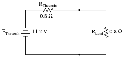
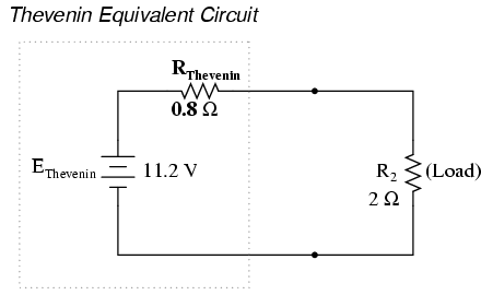
Since Thevenin's and Norton's Theorems are two equally valid methods of reducing a complex network down to something simpler to analyze,Consider the figure below which schematically represents the two-terminal network of constant emf's and resistances; a high-resistance voltmeter, connected to the accessible terminals, will indicate the so called open circuit voltage voc. If an extremely low-resistance ammeter is next connected to the same terminals, as in fig.(b), which is so called the short-circuit current iscwill be measured.
 |
| Test circuits for Thevenin's Theorem |
Now the two quantities determined above may be used to represent an equivalent simple network consisting of the single resistance RTH, which is equal to voc/isc. If the resistor RL is connected to the two terminals, the load current of the circuit will be
 Thevenine Equivalent Circuit
Superposition Theorem
The strategy used in the Superposition Theorem is to eliminate all but one source of power within a network at a time, using series/parallel analysis to determine voltage drops (and/or currents) within the modified network for each power source separately. Then, once voltage drops and/or currents have been determined for each power source working separately, the values are all “superimposed” on top of each other (added algebraically) to find the actual voltage drops/currents with all sources active. Let's look at our example circuit again and apply Superposition Theorem to it:

. . and one for the circuit with only the 7 volt battery in effect:


b. Replace emf source vo by a short circuit. This time Io will act independently and I" now will be obtained when the circuit computed.
c. The two values obtained ( I' and I") with emf and current source acting independently will be added to get I = I' + I"
Norton's Theorem


From the fig (b) above of Norton's equivalent circuit, the load current would be
IL = IN RN / RN+RL ---------------2


